- Fatigue Technologies
- Constant Amplitude
- Variable Amplitude
- Finite Element Model
- Multiaxial
- Probabilistic
- High Temperature
- Welded Structures
- Cast Iron
- Fatigue Analyzers
- Finders
- Technical Background
- Small Defect √ Area
- Utilities
- Languages
 日本語
日本語eFatigue gives you everything you need to perform state-of-the-art fatigue analysis over the web. Click here to learn more about eFatigue.
Cast Iron Technical Background
Fatigue Prediction Method for Cast Irons
The method presented in this section is similar in many ways to the strain-life method. Please read the Constant Amplitude Technical Background for the strain-life method first to better understand cast iron fatigue. Here are a few of the similarities:
- Elastic-plastic behavior in stress concentrations control fatigue life.
- Rainflow counting is used to determine damaging events corresponding to closed elastic-plastic hysteresis loops.
- Mean stresses are tracked according to input loading sequences.
- Smith-Watson-Topper parameter accounts for mean stress.
- Neuber' Rule is used to determine notch root stress and strains.
Cast irons such as gray and nodular iron are really composite materials composed of a steel matrix and distributed particles of graphite of different sizes and shapes. In nodular iron, the graphite particles are roughly spherical and fairly consistent in size. In gray iron, crack-like graphite flakes are distributed in clusters throughout the steel matrix. The presence of the graphite makes cast iron more prone to surface cracking and stiffer in compression than in tension. Gray iron exhibits these behaviors more markedly than nodular iron. For these reasons, the monotonic and cyclic stress-strain behavior of cast iron, specifically gray cast iron, is very different and special models are needed to account for these differences.
eFatigue implements the model developed by Downing. Here is a link to Downing's PhD thesis for a more complete description of the model. The background and a brief description of the model is given below.
STRESS/STRAIN RESPONSE
The stress/strain response in cast iron is controlled by the properties of the steel matrix and, more importantly, the details of the graphite morphology. Quantity, distribution, and shape of the free graphite all affect the degree to which the steel matrix is weakened. Other researchers have reported that, for gray iron under tensile loading, properly oriented graphite flakes crack and debond from the matrix. Detailed early studies by Gilbert of the microstructure of gray iron under tensile load indicated that graphite debonding occurs only near the free surface. He made the following observations:
- Curvature in the tensile stress/strain curve is not only associated with elastic and plastic deformation of the matrix, but is also due to volume increase in the spaces occupied by the graphite.
- This volume increase is most pronounced on the specimen surface where graphite flakes, oriented perpendicularly to the load can actually crack or debond from the matrix.
- Gray iron is stiffer in compression than tension because the spaces occupied by the graphite do not see corresponding decreases in volume.
Nodular iron has similar matrix structure to gray iron, but free graphite is in the form of roughly spherical nodules rather than interconnected graphite flakes. Because the internal notch effect of spherical graphite is less severe than for graphite flakes, nodular iron behaves elastically over a considerable stress range in tension and compression. The elastic limit in compression is, however, slightly higher than in tension. This phenomenon is attributed to a greater local stress concentration effect in tension, resulting in plastic deformation at a lower average stress. At tensile stresses above the elastic limit, the volume of spaces occupied by graphite increased due to voids formed in the direction of loading. Contrary to the behavior of gray iron, however, little overall increase in volume occurred under compressive stress. Compacted graphite (CG) cast iron, which possesses a graphite configuration intermediate to that of conventional gray and nodular irons, has recently become recognized as a viable material for commercial production. Mechanical properties of CG irons far surpass those of gray iron, but thermal conductivity, resistance to thermal shock, and machinability are far more similar to gray than nodular irons. Studies of deformation and fatigue resistance of CG irons indicate mechanical properties bounded by those of gray iron and nodular iron.
Monotonic Behavior
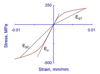
Monotonic stress/strain curves for the range of cast irons from gray to nodular differ greatly in character. Gray iron exhibits highly asymmetrical behavior and neither tensile nor compressive stress/strain curves show definable elastic limits. Nodular irons, on the other hand, remain linearly elastic over a considerable range of stress, and tensile and compressive behavior is nearly identical. In order to to facilitate development of a consistent cyclic deformation model, a single constitutive relationship which adequately represents the monotonic tensile and compressive curves for all cast irons is desirable. Development of such a relationship follows. The model is developed for gray iron, it being the most difficult to model.
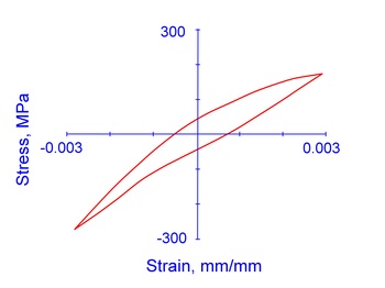
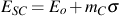
Secant modulus, ES is the slope of a line from the origin to a point on the stress/strain curve. The secant modulus will decrease with the stress level and is different in tension and compression as shown in the figure below. Here we will use the subscript T and C to distinguish between tension and compression behavior. Tension and compression stress strain curves are shown in the following figure.
The secant modulus has a linear relationship with stress over a considerable range as shown in the figure below.
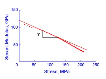
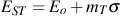
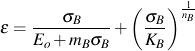
The intercept of the initial straight-line portion at zero stress defines the tangent modulus, Eo, at the origin of the monotonic stress/strain curve. Slope, m, reflects the amount of initial stress/strain curvature. Together these parameters define an expression for the linear portion of the secant modulus curve
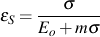
Note that at larger strains there is a deviation from linearity. This can be attributed to plastic strain in the matrix. Total strain, ε, is the sum of secant strain, εS and the remaining plastic strain, εR.

where the secant strain is expressed by
In gray iron, plastic strain occurs at the graphite flake tips at low stress levels due to their high stress concentration factors. Remaining plastic strain is analogous to net section plastic strain in wrought materials. At higher stress levels, the secant modulus/stress curve deviates from linearity, indicating the εR is increasing in magnitude. Remaining plastic strain is determined at each stress level by subtracting the calculated secant strain from total strain.
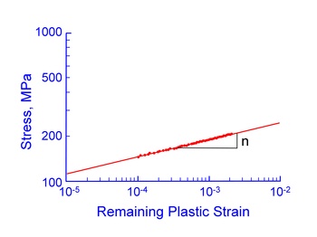
A power law relationship between stress and remaining plastic strain is used in the same manner as stress and plastic strain are related in wrought metals. This yields the following expression for eR as a function of stress

where n is the slope of the curve and K is the intercept at εR = 1. A constitutive equation for the monotonic stress/strain behavior is then obtained as
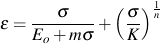
Seven material constants, Eo, mT, KT, nT,mC, KC and nC fare obtained from the tensile and compressive stress strain curves. It should be noted that this equation becomes the well-know Ramberg-Osgood equation used for wrought metals if m is zero. In this case mT = mC and KT = KC.
Despite the number of material constants this constitutive relationship is not, by itself, sufficient for modeling cyclic behavior. Additional information concerning the effects of the free graphite are needed. The next sections describe the individual components of total stress/strain response which are: (1) the symmetrical bulk response, (2) compressive stress due to internal graphite constraint, and (3) compressive stress due to surface crack closure.
Bulk Behavior
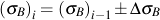
For cyclic deformation consideration must be given to the fraction of load carried by the metal matrix and that portion carried by the graphite. Bulk stress/strain response is dominated by the metal matrix since the metal matrix modulus is much larger than the graphite modulus and the volume fraction of graphite is less than 25%. It is assumed to have characteristics similar to wrought metals in the elastic and plastic regimes. Of primary significance are Masing behavior (where outer loops are the same as initial loading curves if both stresses and strain are multiplied by 2) and material memory (the occurrence of closed hysteresis loops). Using these assumptions, the bulk stress/strain curve will have the same form as the monotonic curves, that is,
where σB is the bulk stress at a given strain, ?, and mB, KB, and nB are material properties. Here the same material properties are used for both tension and compression.
Constitutive equations for bulk stress/strain response under cyclic loading requires an incremental solution.
and
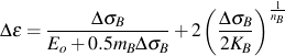
where
The sign of ΔσB is positive for loading and negative for unloading. Selection of material properties mB, KB and nB, will be described in a later section.
Because of the symmetrical nature of the bulk response, additional components of the total response are needed to adequately describe the deformation behavior of graphite flake cast irons. These components, described in the following sections, quantify the effects of internal graphite constraint and surface cracking.
Internal Graphite Behavior
One of the characteristics of cast iron (gray iron in particular) is its greater stiffness in compression than in tension. Under compressive loading, fovorably oriented graphite is constrained such that the graphite approaches incompressibility. Additional compressive stress is transferred to to the inherently stiffer matrix; therefore, a component of stress which accounts for this phenomenon must be defined. Addition of the stress, σG, and the bulk stress in compression must result in the monotonic compressive stress/strain curve. Therefore, σG may be expressed by

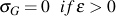
where σC is the monotonic compressive response and σB is the bulk response in compression. This stress partially accounts for the inflection point on the unloading potion of some gray and CG iron hysteresis loops. Also, it is considered nonlinear elastic and dependent only on the compressive strain.
For low compressive strain, this graphite stress may be determined directly from the secant components of the bulk compressive stress/strain curves. When compressive strains are of sufficient magnitude that the remaining plastic strain components are no longer negligible, an iterative approach is required.
Surface Behavior
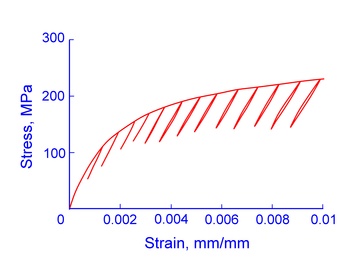
Numerous researchers have detected crack-like defects (debonded graphite) on the surface of cast iron specimens loaded in tension. Phenomenologically, this is significant, for it results in changes of specimen compliance at high tensile stresses. Decreases in the unloading modulus from tensile peaks of flake iron hysteresis loops are evidence of these changes. The following figure shows that the unloading modulus modulus decreases with increasing stress for gray cast iron.
Unloading modulus, EU, and maximum stress for each hysteresis loop in in the figure above correlate as shown below.
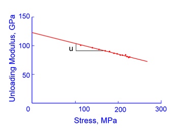
A linear relationship is indicated resulting in
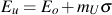
where mU is the slope. The tangent modulus at zero stress, Eo, is indistinguishable form the tangent modulus of the monotonic stress/strain curve and is therefore considered equivalent.
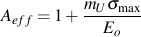
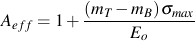
Differences in the elastic modulus of steel and cast iron reflect a reduced effective cross-sectional area for cast iron specimens due to the presence of free graphite. Similarly, the decrease in unloading modulus, which results from surface cracking, is evidence of further degradation in effective area. It is useful then to define a dimensionless parameter, Aeff, to be the fraction of cross-sectional area unaffected by surface cracking. For an unstressed cast iron specimen, Aeff is assumed equal to unity. Since surface cracking is reflected in decreased unloading modulus, Aeff is expressed by

or by substituting
Bulk behavior, described earlier, is the symmetrical response of the metal matrix and graphite without the effects of graphite constraint and surface cracking. Graphite stress, σG, is nonzero only for compressive strains. Therefore, the stress reached by cast iron under monotonic tensile loading must be the product of bulk stress and the effective area fraction or

Manipulation of equations for low tensile stress levels results in
and

The other bulk material properties, KB and nB, can be determined as follows
- Determine monotonic tensile stress at a number of strain levels
- Calculate corresponding Aeff's for each strain level
- Calculate corresponding σB's
- Calculate the bulk remaining plastic strain
- Perform linear regression on log σB vs. log εR to obtain KB and nB.
At some point during unloading, open surface cracks close and add compressive stress to the overall response. Therefore, a stress component, σCC, due to crack closure must be defined. Mathematical formulation of this stress of this stress is given in the next section.
Cyclic Strain/Strain Response Model
The total stress/strain model for cast iron under cyclic loading is given by

The first term, Aeff (σB+σG), represents the bulk and graphite stresses acting over the fraction of cross-sectional area unaffected by surface cracking. The second term, (1-Aeff)σCC is the compressive crack closure stress acting over the remaining area. All terms have been defined previously with the exception of .
A power-law relationship is an effective and convenient formulation of the crack closure stress:
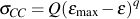
where Q and q are new constants which depend on monotonic material properties and the strain limits. Crack closure stress, σCC, is considered nonlinear elastic.
Under completely-reversed strain cycling, the peak tensile and compressive stresses generally lie on the monotonic tensile and compressive curves, respectively. Thus, neither σCC nor the graphite stress, σG, contribute to hysteresis energy in cast iron; if so, the elastic/plastic bulk response must then be the sole cause of the area (energy) in cast iron hysteresis loops. The imposition of Masing behavior on bulk response dictates that, for this model, the distribution of hysteresis energy must be symmetrical with respect to the mean strain of a hysteresis loop. Stated another way, the height of cast iron hysteresis loops must be a maximum at and symmetrical about the mean strain. These boundary conditions allow the constants Q and q to be evaluated directly from the stress strain curves.
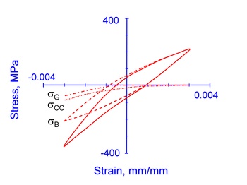
The following figure shows the total and individual components of stress/strain response for a representative gray iron hysteresis loop.
Material Property Tests
The cyclic deformation model presented accurately predicts the initial stress/strain response of cast iron under variable loading. Eight material constants (mT, KT, nT, mC, KC, nC, mU and Eo) are needed compared with four needed for wrought materials (with the same properties in tension and compression).
These can be obtained from the following three tests:
- Monotonic tensile test
- Monotonic compressive test
- Incremental loading test to determine the unloading modulus parameter
An estimate of the unloading modulus data could also be obtained from hysteresis loop data.
FATIGUE TEST DATA
The relationship between loading parameters and cycles to failure for cast irons should, in some way, account for the surface crack phenomenon. Smith, Watson and Topper suggested a parameter, the product of the maximum stress and stain amplitude in a hysteresis loop, to include the effects of mean stress and early crack growth for fatigue in metals. The following figure shows this parameter plotted against cycles to failure for pearlitic gray iron under a variety of testing conditions. Peak stress and strain amplitude can be measured initially or at the half life with equally good correlation.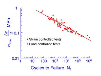
This parameter not only accounts for mean stress, but also provids a single relationship for both load-control and strain-control data. Unlike wrought materials, a single straight line fits the data reasonably well with two material constants for the slope and intercept.
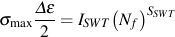
where σmax is maximum tensile stress and Δε/2 is the strain amplitude.