- Fatigue Technologies
- Constant Amplitude
- Variable Amplitude
- Finite Element Model
- Multiaxial
- Probabilistic
- High Temperature
- Welded Structures
- Fatigue Analyzers
- BS 7608
- International Institute
of Welding - Aluminum Association
- Strain-Life
- Crack Growth
- Probabilistic BS 7608
- Probabilistic Crack Growth
- VA BS 7608
- VA International Institute
of Welding - VA Aluminum Association
- VA Crack Growth
- Finders
- Technical Background
- Cast Iron
- Small Defect √ Area
- Utilities
- Languages
 日本語
日本語eFatigue gives you everything you need to perform state-of-the-art fatigue analysis over the web. Click here to learn more about eFatigue.
Aluminum Association Welds Technical Background
Welds may be analyzed with any fatigue method, stress-life, strain-life or crack growth. Use of these methods is difficult because of the inherent uncertainties in a welded joint. For example, what is the local stress concentration factor for a weld where the local weld toe radius is not known? Similarly, what are the material properties of the heat affected zone where the crack will eventually nucleate. One way to overcome these limitations is to test welded joints rather than traditional material specimens and use this information for the safe design of a welded structure.
Weld Classifications
For purposes of evaluating fatigue, weld joints are divided into several classes. The classification of a weld joint depends on:
- the macroscopic geometry of the pieces welded,
- the direction of the cyclic stresses, and
- the location of the crack that leads to failure.
Two fillet welds are shown below. One is loaded parallel to the weld toe ( Class D ) and the other loaded perpendicular to the weld toe ( Class F2 ).
It is then assumed that any complex weld geometry can be described by one of the standard classifications.
Material Properties
One of the most comprehensive sources for designing aluminum structures is the Aluminum Association's Specifications for Aluminum Structures in the Aluminum Construction Manual. It provides standard SN curves for aluminum welds.
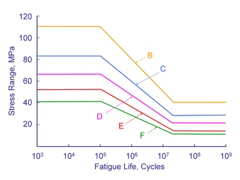
The curves shown above are valid for structural aluminum welds. Fatigue lives are not dependant on either the alloy or the applied mean stress. Welds are known to contain small cracks from the welding process. As a result, the majority of the fatigue life is spent in growing these small cracks. Fatigue lives are not dependant on the alloy because all weldable aluminums have about the same crack growth rate. The crack growth rate in aluminum is about ten times faster than steel and aluminum welds have much lower fatigue resistance. Welding produces residual stresses at or near the yield strength of the material. The as welded condition results in the worst possible residual or mean stress and an external mean stress will not increase the weld toe stresses because of plastic deformation. Fatigue lives are computed from a simple power function.

The constant C is the intercept at 1 cycle and is tabulated in the standard. This constant is much larger than the ultimate strength of the material.
The standard is only valid for fatigue lives in excess of 105 cycles and limits the stress to 80% of the yield strength. Experience has shown that the SN curves provide reasonable estimated for higher stress levels and shorter lives. In eFatigue, the maximum stress range permitted is limited by the allowable stress for plane plate for all weld classes.